
Specialist Steel Structure Solutions
Multi-Storey Steel Buildings
Steel framing solutions for offices, towers, hotels, residential and mixed-use buildings where speed, column-free space and coordinated services matter.
Solution Overview
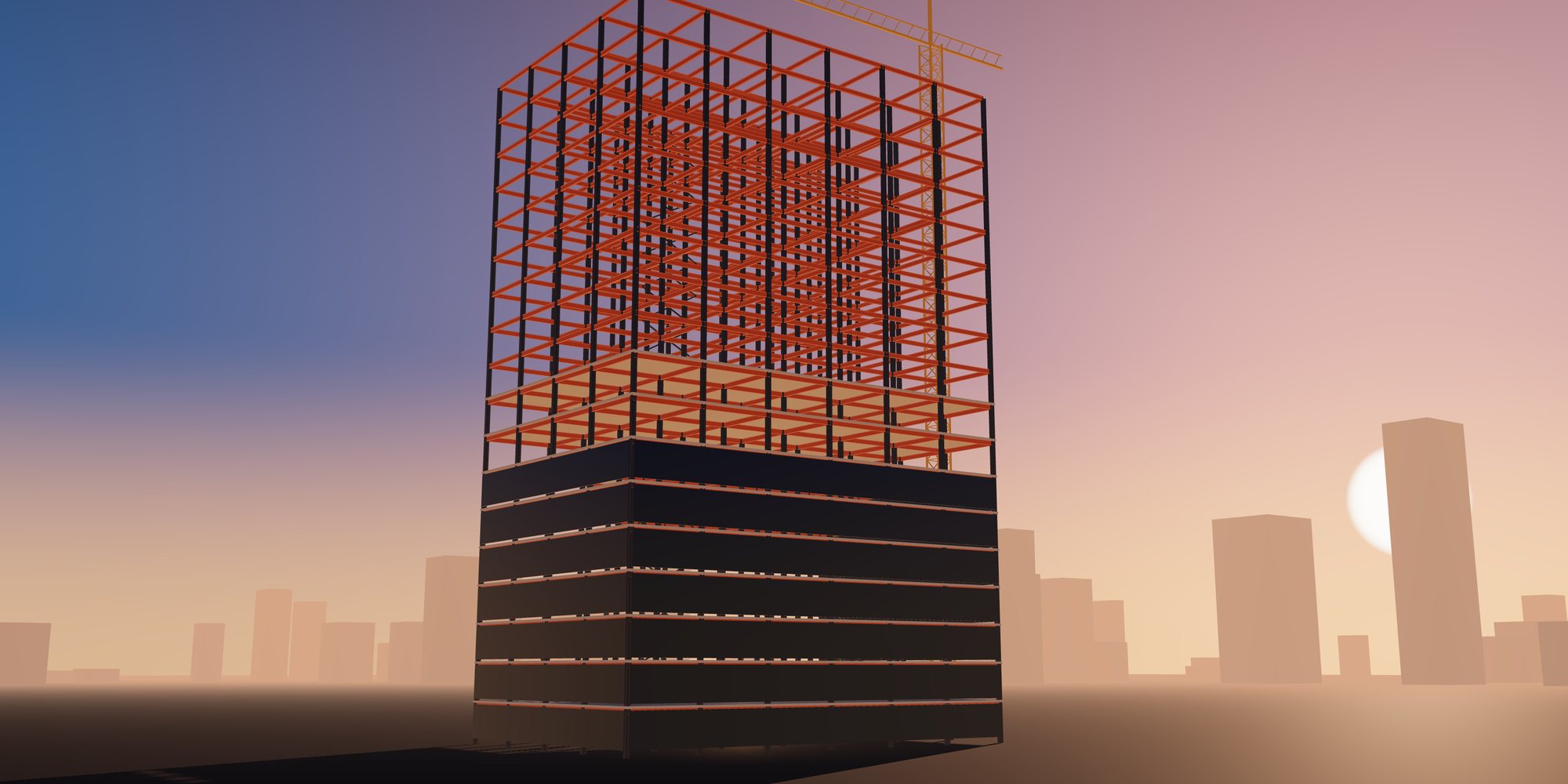
Multi-storey steel buildings combine moment, braced or composite frames with composite or precast floor systems. Steel framing allows long clear spans, lighter foundations and a high degree of off-site fabrication, which shortens the on-site programme.
Early coordination of the structural grid, floor depth, service penetrations and fire protection strategy has the largest influence on cost and buildability.
Typical Applications
- Office Buildings
- High-Rise Steel Buildings
- Commercial Towers
- Mixed-Use Developments
- Hotels
- Residential Steel Buildings
- Parking Structures
- Composite Steel Buildings
Sector challenges
Challenges We Engineer For
Controlling drift on slender frames
Our engineering response We compare core, outrigger and moment frame options early and size members for stiffness as well as strength, so drift is resolved without late tonnage increases.
Floor vibration in open-plan spaces
Our engineering response Floor systems are checked for occupant-induced vibration using composite stiffness and realistic damping, and beam depth or spacing is adjusted before drawings are issued.
Service integration within limited floor depth
Our engineering response We coordinate web openings with the MEP model and reinforce openings only where needed, keeping the ceiling zone shallow.
Fast floor cycles on site
Our engineering response Standardized bolted connections, floor-by-floor packing and clear erection marks let the contractor install complete levels with minimal site welding.
Engineering Solutions
Our engineering team builds a full three-dimensional analysis model of the frame, combining gravity, wind, seismic and notional loads with construction-stage cases for partially completed floors. Lateral systems are compared early, braced cores against moment frames or hybrid arrangements, so that drift, floor-to-floor height and architectural openness are balanced before the grid is frozen. Composite beam and slab interaction is modeled explicitly to capture stiffness and vibration behavior under occupancy.
Connections are designed to the code basis named for the project, whether AISC 360 with ASCE 7 loading, CSA S16, AS 4100 or Eurocode 3. We standardize simple shear connections across typical floors, detail moment and brace connections for capacity design where seismic provisions apply, and locate column splices to suit crane reach, transport length and the erection sequence agreed with the contractor.
Engineering Considerations
- Lateral system selection (braced cores, moment frames or composite cores) and drift limits
- Floor vibration and serviceability under occupancy loads
- Fire resistance strategy per local building code
- Column splice locations and erection sequence for tall frames
- Integration of building services through beam web openings
One coordinated scope
From Engineering to Delivery on Site
Design optimization, fabrication, quality control, surface protection, export logistics and erection support managed as one scope, so interfaces between design, shop and site stay under control.
-
Design Optimization
In multi-storey frames the largest savings come from repetition and floor depth. We rationalize beam sizes into a small family of sections, tune composite action to reduce beam weight, and test alternative grids for their effect on column tonnage and foundation loads. Planned web openings let services pass through beams instead of under them, which can reduce overall building height. Column sizes are stepped at splice levels, and connection types are chosen to minimize site welding and speed up floor-by-floor installation.
-
Fabrication Solutions
Typical members include rolled columns with shop-welded splice plates, composite floor beams with stud layouts and cambers, cellular or castellated beams, and braced core elements with gusset assemblies. Moment connections and column base plates receive full-penetration or fillet welds to qualified procedures under the AWS D1.1, AS/NZS 1554.1 or EN 1090 requirements specified. Each piece is marked with its grid, level and erection mark so that crews can install floor packages in sequence without searching the laydown area.
Hole patterns for deck fixings, edge trims and service openings are cut by CNC from the BIM model to keep alignment between floors consistent. Beam cambers are induced in the shop where the design calls for them, and stud positions are marked or pre-welded to suit the deck layout. Column lengths are controlled carefully at splices so that accumulated tolerances over many storeys stay within the limits needed for plumb, level floors.
-
Quality Assurance
Each project runs to an inspection and test plan that sets hold and witness points for material receipt, fit-up, welding and coating. Plates and sections are traced to mill certificates through heat numbers recorded against piece marks. Ultrasonic testing is applied to complete-penetration welds at moment and splice connections, with magnetic particle testing for fillet welds where required. Column lengths, splice squareness and connection hole positions are checked dimensionally, and results are compiled into a quality dossier issued with each delivery batch.
-
Surface Protection
Most framing in occupied buildings sits in a mild interior environment, so a shop primer compatible with the specified fire protection system is often sufficient. Exposed perimeter steel, podium transfer members and parking levels may need a full ISO 12944 system suited to C3 or C4 exposure. We coordinate primers with intumescent coatings or board systems, keep top flanges uncoated where shear studs will be welded, and mask faying surfaces of slip-critical bolted connections to the class required.
-
Export & Logistics
Steel is packed and shipped by floor and erection zone, so that columns, beams and bracing for one tier arrive together. Long columns and heavy transfer girders are planned for flat rack or break-bulk shipment, while connection plates, bolts and studs travel in labeled crates within standard containers. Each shipment carries a packing list cross-referenced to erection drawings, plus the commercial invoice, certificate of origin and other export documents needed for customs clearance at the destination port.
-
Erection Support
We provide erection drawings showing piece marks, bolt schedules and splice details for every level, together with a recommended sequence that keeps the frame stable as floors are added. Our engineers give input to the erection contractor method statements on temporary bracing, deck installation order and column plumbing tolerances. Where agreed, we offer technical supervision or remote advisory support to resolve fit-up questions quickly. Erection itself is carried out by the appointed contractor.
What You Receive
Typical engineering, fabrication and quality documents for this type of structure. The final list is agreed for each project.
- Design basis report with load cases and lateral system rationale
- Structural calculation report and analysis model
- Connection design calculations for shear, moment and brace connections
- IFC general arrangement drawings by floor
- Coordinated BIM model with service openings
- Shop drawings and floor-by-floor erection drawings
- ITP, weld and NDT records and mill certificates
- Packing lists sequenced by erection zone
Global supply
Supplying Projects Worldwide
Engineering and documentation aligned with the codes, approvals and logistics of each market we supply.
-

Steel Structures for the United States
Structural steel for US projects designed and documented to AISC, ASCE 7 and AWS practice, with the submittals and traceability US…
-

Steel Structures for Canada
Steelwork for Canadian projects to CSA S16 design and CSA W59 welding, with welding-company certification and cold-climate material…
-

Steel Structures for Australia
Fabricated steel for Australian projects to AS 4100, AS/NZS 5131 and AS/NZS 1554.1, with construction category, cyclone wind actions and…
-

Steel Structures for New Zealand
Seismic-ready steelwork for New Zealand to NZS 3404 design and AS/NZS 5131 fabrication, with ductility, connection capacity design and…
-


Steel Structures for Europe
Structural steel components for European projects designed to the Eurocodes with National Annexes, and executed to EN 1090 with the…
-

Steel Structures for Japan
Steel supply for Japanese projects under the Building Standards Act framework, JIS-designated materials and fabricator grading, with…
-

Steel Structures for South Korea
Steelwork for Korean industrial and building projects aligned with the Korean Building Code and KS material standards, with fast-track…
-


Steel Structures for Southeast Asia
Regional steel supply across Singapore, Malaysia, Thailand, Vietnam, Indonesia and the Philippines, where each country's code basis…
-


Steel Structures for the Middle East
Steelwork for Gulf and Middle East projects specified to international codes by consultants, with extreme heat, sand and saline exposure…
-
Other International Markets
For markets not listed separately, we start from the project specification: governing code, material standards, inspection regime and…
Frequently Asked Questions
Can you work with a concrete core designed by another engineer?
Yes. We design the steel framing around the core and coordinate embed plates, connection loads and tolerances with the core designer. Interface loads are documented clearly so both parties work from the same information.
Which floor system works best with your steel frames?
Composite metal deck is common because it is light and fast to install, but we also design for precast planks and hollowcore. We compare options for span, depth, fire rating and schedule, then recommend the system that suits the building and local construction practice.
How do you handle fire protection on exposed beams?
We confirm the required fire resistance with the design team and coordinate a primer compatible with the chosen intumescent or board system. Section factors are reported so the fire protection supplier can specify thickness accurately.
Discuss Your Multi-Storey Steel Buildings Project
Share your drawings and requirements. Our engineering team reviews the scope, the governing design code and the delivery conditions, then responds with the next steps.
Helpful to include
- Architectural or structural drawings, or a sketch of the layout
- Project location and site conditions
- Governing design code and any client specifications
- Key loads: cranes, equipment, wind or seismic data if known
- Required scope: design, fabrication, coating, supply, erection support
- Target schedule and delivery terms
Files attached to the request form are stored privately and are visible only to authorized staff.