
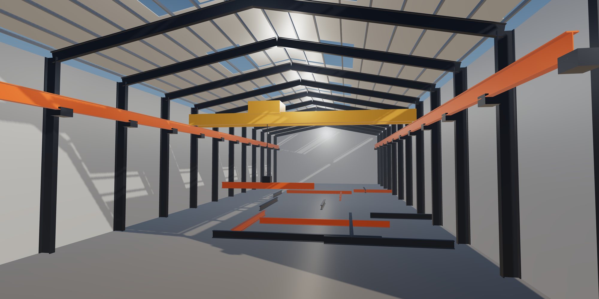
Specialist Steel Structure Solutions
Pre-Engineered Steel Buildings
Pre-engineered building (PEB) systems for warehouses, factories, workshops, logistics and agricultural buildings.
Solution Overview
Pre-engineered buildings use tapered built-up primary frames with cold-formed secondary members (purlins and girts) and metal cladding. Members are optimised for the specific load case, which gives efficient steel weight for regular, single-storey buildings.
PEB is best suited to rectangular plans with repeating frames; complex geometry or heavy cranes may call for conventional framing.
Typical Applications
- PEB Warehouses
- PEB Factories
- PEB Workshops
- PEB Logistics Facilities
- PEB Agricultural Buildings
Sector challenges
Challenges We Engineer For
Wind uplift on lightweight roofs
Our engineering response We design purlins, bridging and frame flanges for uplift and verify flange restraint so that reversed loading does not govern unexpectedly.
Large doors and internal pressure
Our engineering response Dominant openings are accounted for in internal pressure cases, and door framing is designed for the full wind load and deflection limits of the door supplier.
Adding mezzanines or light cranes
Our engineering response Mezzanine and crane loads are included in the frame design from the start, with brackets and columns sized for the actual equipment.
Fast delivery for remote sites
Our engineering response Containerized packing by gridline and clear erection marks help local crews assemble the building without specialist equipment.
Engineering Solutions
Pre-engineered buildings are designed frame by frame. Our engineering team analyzes tapered primary frames for dead, collateral, roof live, snow, wind and seismic loads, with particular attention to wind uplift, internal pressure from large doors and unbalanced snow or drift at roof steps. Secondary members are designed as cold-formed purlins and girts with lapped or continuous behavior and restraint from cladding and bridging, while end walls are framed for wind loads and future extension.
Connections are typically bolted end plates at knees and ridges, flush or extended depending on moment demand, designed to AISC 360, CSA S16, AS 4100 or Eurocode 3 as specified. Bracing systems, whether rod, cable or angle, are arranged to carry longitudinal wind and seismic forces into foundations.
Engineering Considerations
- Frame span, eave height and bay spacing optimisation
- Wind uplift on roof and cladding, and purlin restraint
- Serviceability limits for cladding and doors
- Compatibility with mezzanines and light cranes
One coordinated scope
From Engineering to Delivery on Site
Design optimization, fabrication, quality control, surface protection, export logistics and erection support managed as one scope, so interfaces between design, shop and site stay under control.
-
Design Optimization
PEB efficiency depends on tuning geometry to the load. We optimize frame spacing, eave height and roof slope together, adjust web taper and flange sizes along each rafter, and select purlin depth and gauge to suit the bay. Multi-span frames with interior columns are compared with clear-span options where the use permits. Standardizing door and opening framing, and limiting the variety of secondary profiles, reduces fabrication setups and simplifies site installation.
-
Fabrication Solutions
Primary frames are built up from plate with automated or semi-automated welding of flanges to tapered webs, typically using single-sided or double-sided fillet welds to the AWS D1.1, AS/NZS 1554.1 or EN 1090 requirements specified. Purlins and girts are roll-formed to profile with punched holes for bolting and bridging. End plates are drilled to templates to keep frame alignment consistent.
Every frame, purlin and bracing member is marked with its gridline and position so that site crews can assemble the building quickly. Knee and ridge splices are drilled as matched pairs to avoid site reaming. Framed openings, door jambs and canopy brackets are fabricated with the primary steel, so the complete building kit, including flange braces and sag rods, leaves the shop as a coordinated set.
-
Quality Assurance
Our inspection and test plan covers plate and coil receipt, web-to-flange welding, end plate flatness and hole positions, and coating thickness. Mill certificates for plate, coil and bolts are retained and linked to production batches. Visual inspection is applied to all welds, with ultrasonic or magnetic particle testing at end plate and knee connections as specified. Dimensional checks confirm member length, taper geometry and hole alignment, and the records are compiled into a quality dossier for each building.
-
Surface Protection
Primary frames usually receive a shop primer or a full ISO 12944 system suited to the internal environment, commonly C2 or C3. Agricultural buildings, fertilizer stores or coastal warehouses may require C4 or C5 systems, or hot-dip galvanizing to ISO 1461. Secondary members are commonly supplied in pre-galvanized coil. Fire protection is applied only where the building code or insurer requires it, and we coordinate that early to avoid late changes.
-
Export & Logistics
PEB components are compact and well suited to export. Frames are nested, purlins and girts are bundled by length, and bolts, anchor bolts and accessories are boxed by building and gridline, so most buildings ship in standard containers. Loading is planned so that anchor bolts and the first frames arrive first. Each shipment includes packing lists keyed to erection drawings, plus the commercial and customs documents required for import at destination.
-
Erection Support
We supply anchor bolt plans, erection drawings and bolt schedules that show every frame, purlin and bracing member in position. Our engineers provide input to method statements covering frame lifting, temporary bracing of the first braced bay and purlin installation order. Remote advisory support or site technical supervision can be arranged when agreed. The building is erected by the contractor appointed by the client.
What You Receive
Typical engineering, fabrication and quality documents for this type of structure. The final list is agreed for each project.
- Design basis report and load summary
- Frame and secondary member calculation report
- Anchor bolt plan and foundation reaction schedule
- IFC general arrangement and cladding layout drawings
- Shop drawings and erection drawings with bolt schedules
- ITP, weld inspection records and mill certificates
- Container packing lists keyed to gridlines
Global supply
Supplying Projects Worldwide
Engineering and documentation aligned with the codes, approvals and logistics of each market we supply.
-

Steel Structures for the United States
Structural steel for US projects designed and documented to AISC, ASCE 7 and AWS practice, with the submittals and traceability US…
-

Steel Structures for Canada
Steelwork for Canadian projects to CSA S16 design and CSA W59 welding, with welding-company certification and cold-climate material…
-

Steel Structures for Australia
Fabricated steel for Australian projects to AS 4100, AS/NZS 5131 and AS/NZS 1554.1, with construction category, cyclone wind actions and…
-

Steel Structures for New Zealand
Seismic-ready steelwork for New Zealand to NZS 3404 design and AS/NZS 5131 fabrication, with ductility, connection capacity design and…
-


Steel Structures for Europe
Structural steel components for European projects designed to the Eurocodes with National Annexes, and executed to EN 1090 with the…
-

Steel Structures for Japan
Steel supply for Japanese projects under the Building Standards Act framework, JIS-designated materials and fabricator grading, with…
-

Steel Structures for South Korea
Steelwork for Korean industrial and building projects aligned with the Korean Building Code and KS material standards, with fast-track…
-


Steel Structures for Southeast Asia
Regional steel supply across Singapore, Malaysia, Thailand, Vietnam, Indonesia and the Philippines, where each country's code basis…
-


Steel Structures for the Middle East
Steelwork for Gulf and Middle East projects specified to international codes by consultants, with extreme heat, sand and saline exposure…
-
Other International Markets
For markets not listed separately, we start from the project specification: governing code, material standards, inspection regime and…
Frequently Asked Questions
When is a PEB the right choice instead of conventional steel?
PEB works best for single-storey buildings with regular, repeating frames and moderate loads, such as warehouses and workshops. Heavy cranes, complex geometry or many openings can make conventional framing more economical. We can compare both approaches for your layout.
Can the building be extended in the future?
Yes. We can design an end wall as an expandable frame so that it can carry future rafters, and leave bracing and foundations arranged for added bays. Telling us about expansion plans early keeps the extension straightforward.
What information do you need for a quotation?
We need building dimensions, eave height, roof slope preference, location for wind, snow and seismic data, door and opening positions, and any cranes or mezzanines. Cladding type and corrosion environment help us refine the offer.
Discuss Your Pre-Engineered Steel Buildings Project
Share your drawings and requirements. Our engineering team reviews the scope, the governing design code and the delivery conditions, then responds with the next steps.
Helpful to include
- Architectural or structural drawings, or a sketch of the layout
- Project location and site conditions
- Governing design code and any client specifications
- Key loads: cranes, equipment, wind or seismic data if known
- Required scope: design, fabrication, coating, supply, erection support
- Target schedule and delivery terms
Files attached to the request form are stored privately and are visible only to authorized staff.