
Specialist Steel Structure Solutions
Industrial Steel Buildings
Steel structures for manufacturing plants, production facilities and workshops, including crane-supported buildings.
Solution Overview
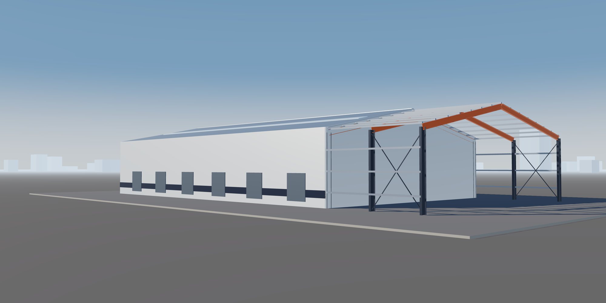
Industrial buildings are typically portal-frame or truss-roof structures sized around process layout, clear height and material handling. Where overhead cranes are present, crane runway girders, brackets and fatigue-sensitive details govern a significant part of the design.
Future expansion, equipment loads and maintenance access should be defined at the concept stage.
Typical Applications
- Manufacturing Plants
- Production Facilities
- Industrial Workshops
- Heavy Manufacturing Buildings
- Assembly Plants
- Crane-Supported Buildings
Sector challenges
Challenges We Engineer For
Fatigue in crane runway girders
Our engineering response We classify crane duty, design girders and details for fatigue, and avoid abrupt stiffener terminations and intermittent welds in tension zones.
Building deflection affecting crane operation
Our engineering response Frame stiffness is checked against crane manufacturer tolerances so rail gauge and alignment remain within limits under load.
Process changes after design starts
Our engineering response We hold a clear design basis for equipment and crane loads and use a parametric model that can absorb layout changes with limited rework.
Future plant expansion
Our engineering response Gable frames, foundations and bracing are arranged so that new bays can be added without dismantling existing primary steel.
Engineering Solutions
Industrial buildings are analyzed around the process they house. Our engineering team models portal frames or truss roofs with crane loads, including vertical wheel loads, lateral surge, longitudinal braking and the combination of multiple cranes, alongside wind, snow, seismic and equipment loads. Crane runway girders are checked for fatigue over the expected duty cycle, and building deflections are verified against the crane manufacturer tolerances so that rails stay aligned in service.
Connection design focuses on crane brackets, runway girder seats, column bases with shear keys and roof bracing nodes. We work to AISC 360, CSA S16, AS 4100 or Eurocode 3 as specified, with fatigue-sensitive details treated carefully so that weld toes, stiffener terminations and rail clips do not become crack initiation points.
Engineering Considerations
- Crane classification, wheel loads and runway girder fatigue
- Clear height, bay spacing and expansion provisions
- Equipment and process loads on roof and mezzanines
- Building envelope and thermal or acoustic requirements
- Corrosion environment inside process areas
One coordinated scope
From Engineering to Delivery on Site
Design optimization, fabrication, quality control, surface protection, export logistics and erection support managed as one scope, so interfaces between design, shop and site stay under control.
-
Design Optimization
Savings in industrial buildings come from matching structure to the process layout rather than imposing a uniform grid. We test bay spacing, stepped or laced crane columns and truss versus portal roofs against tonnage and foundation cost. Runway girders are sized for the actual crane class instead of a conservative default, and roof bracing is arranged to share load paths with crane longitudinal bracing. Provision for future extension is built into gable frames so expansion does not require removing primary steel.
-
Fabrication Solutions
Typical members include built-up or rolled crane columns, welded runway girders with full-penetration top flange welds, cap channels, surge girders, roof trusses and portal rafters. Crane girders receive particular attention to camber, flange flatness and web-to-flange weld quality under the AWS D1.1, AS/NZS 1554.1 or EN 1090 execution class specified. Bearing surfaces and bracket seats are machined or carefully fitted where required.
Roof trusses and crane columns too large to ship whole are trial-assembled where specified to confirm geometry, then split into transport sections with bolted splices. Crane brackets are positioned from a common datum so that rail elevations stay consistent along the runway. Each girder, bracket and truss section carries an erection mark and orientation arrow, reducing the risk of a member being installed reversed on site.
-
Quality Assurance
Our inspection and test plan places hold points on crane girder fabrication, including flange welds, stiffener fit-up and camber. Materials are traced through mill certificates to piece marks, with notch toughness verified where fatigue or low service temperatures apply. Ultrasonic testing covers full-penetration welds on runway girders and brackets, supported by magnetic particle testing at stiffener ends. Dimensional checks confirm girder straightness, bracket elevations and base plate hole patterns, and all records are compiled into a project quality dossier.
-
Surface Protection
Process areas vary widely, from dry assembly halls to humid or chemically aggressive environments. We assess each zone and select an ISO 12944 coating system for the relevant corrosivity category, typically C2 to C4, with higher categories for washdown or chemical areas. Hot-dip galvanizing to ISO 1461 suits secondary steel and external structures. Coating is kept off crane rail seats where it would affect load transfer, and fire protection is applied only where the building code requires it.
-
Export & Logistics
We sequence delivery so that columns, crane girders and roof steel for each bay arrive in the order the contractor intends to erect. Long crane girders and roof trusses are typically shipped break-bulk or on flat racks, while purlins, girts, bracing and bolts are bundled and containerized. Bundles carry tags matching erection drawings, and each consignment is accompanied by packing lists, commercial invoices and certificates of origin for customs and site receipt.
-
Erection Support
Our erection drawings show column setting, girder placement, bracing installation and rail alignment requirements for each bay. We provide input to method statements on lifting heavy crane girders, temporary stability of portal frames before roof bracing is complete, and survey checks before rail fixing. When agreed, our engineers attend site or support remotely during critical stages such as crane girder installation. Site erection is performed by the contractor appointed by the client.
What You Receive
Typical engineering, fabrication and quality documents for this type of structure. The final list is agreed for each project.
- Design basis report covering crane, process and environmental loads
- Structural calculation report including crane girder fatigue checks
- Connection design calculations for brackets, bases and bracing
- IFC general arrangement drawings and crane girder layouts
- BIM model coordinated with process equipment
- Shop drawings and bay-by-bay erection drawings
- ITP, NDT reports and mill certificates
- Packing lists and shipping documentation
Global supply
Supplying Projects Worldwide
Engineering and documentation aligned with the codes, approvals and logistics of each market we supply.
-

Steel Structures for the United States
Structural steel for US projects designed and documented to AISC, ASCE 7 and AWS practice, with the submittals and traceability US…
-

Steel Structures for Canada
Steelwork for Canadian projects to CSA S16 design and CSA W59 welding, with welding-company certification and cold-climate material…
-

Steel Structures for Australia
Fabricated steel for Australian projects to AS 4100, AS/NZS 5131 and AS/NZS 1554.1, with construction category, cyclone wind actions and…
-

Steel Structures for New Zealand
Seismic-ready steelwork for New Zealand to NZS 3404 design and AS/NZS 5131 fabrication, with ductility, connection capacity design and…
-


Steel Structures for Europe
Structural steel components for European projects designed to the Eurocodes with National Annexes, and executed to EN 1090 with the…
-

Steel Structures for Japan
Steel supply for Japanese projects under the Building Standards Act framework, JIS-designated materials and fabricator grading, with…
-

Steel Structures for South Korea
Steelwork for Korean industrial and building projects aligned with the Korean Building Code and KS material standards, with fast-track…
-


Steel Structures for Southeast Asia
Regional steel supply across Singapore, Malaysia, Thailand, Vietnam, Indonesia and the Philippines, where each country's code basis…
-


Steel Structures for the Middle East
Steelwork for Gulf and Middle East projects specified to international codes by consultants, with extreme heat, sand and saline exposure…
-
Other International Markets
For markets not listed separately, we start from the project specification: governing code, material standards, inspection regime and…
Frequently Asked Questions
What crane information do you need to start design?
We need crane capacity, span, duty class, wheel loads and spacing, hook approach and the manufacturer tolerance requirements. If the crane supplier is not yet appointed, we can work from a defined design envelope and verify once final data is available.
Can you design mezzanines and equipment platforms inside the building?
Yes. Mezzanines, platforms and equipment supports are included in the same model so that their loads flow consistently into columns and foundations. This avoids conflicts between building steel and process steel.
Do you supply the cladding and roofing?
Our scope is the structural steel, including purlins, girts and framed openings. We coordinate cladding fixings, opening details and loads with the envelope supplier so the steel is ready to receive the cladding system.
Discuss Your Industrial Steel Buildings Project
Share your drawings and requirements. Our engineering team reviews the scope, the governing design code and the delivery conditions, then responds with the next steps.
Helpful to include
- Architectural or structural drawings, or a sketch of the layout
- Project location and site conditions
- Governing design code and any client specifications
- Key loads: cranes, equipment, wind or seismic data if known
- Required scope: design, fabrication, coating, supply, erection support
- Target schedule and delivery terms
Files attached to the request form are stored privately and are visible only to authorized staff.