
Specialist Steel Structure Solutions
Infrastructure Steel Structures
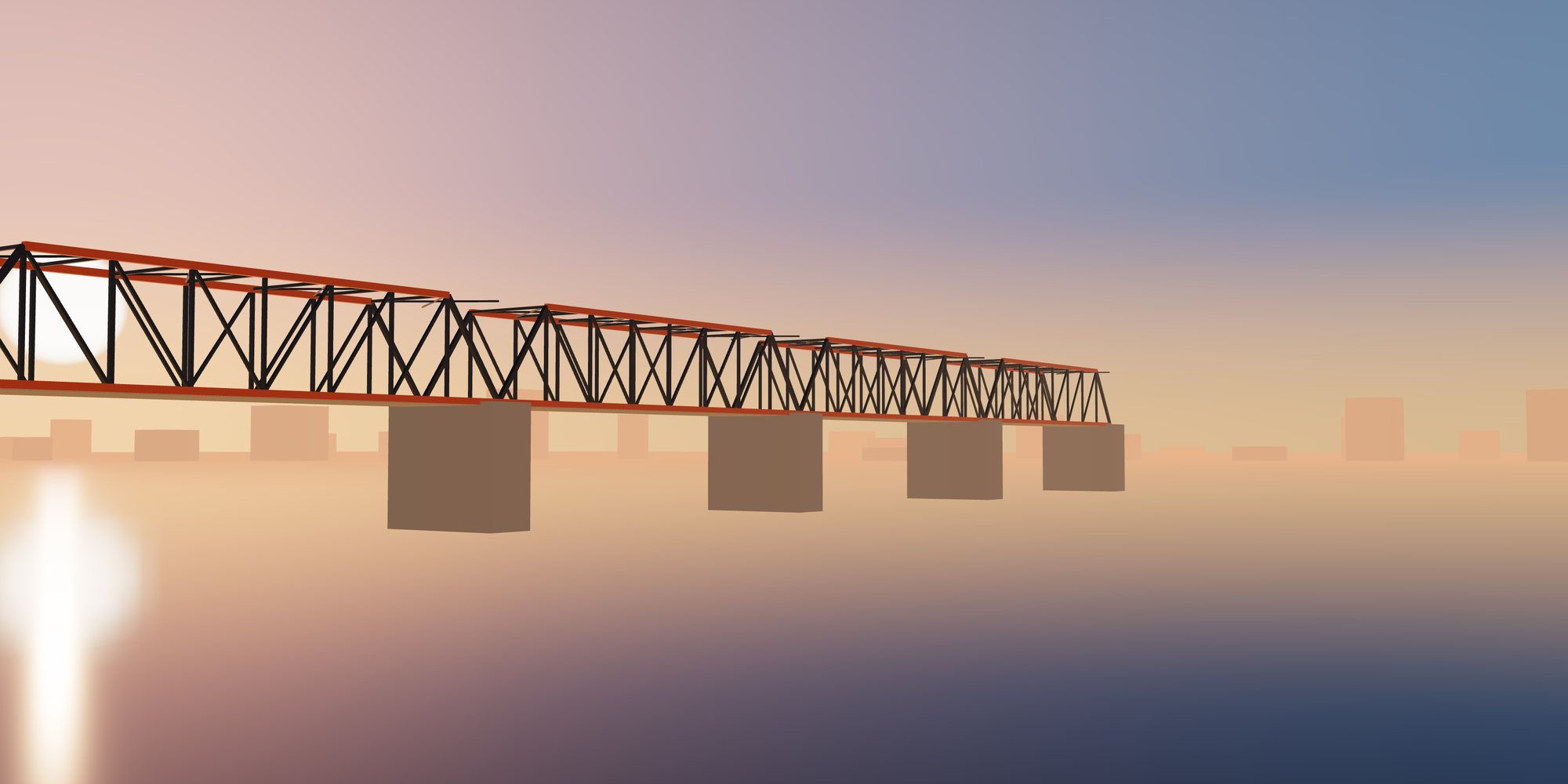
Steelwork for pedestrian bridges, bridge components, transportation and utility structures.
Solution Overview
Infrastructure steelwork is governed by owner and road or rail authority specifications in addition to structural standards. Fatigue, durability over long design lives and inspection access are key considerations.
Typical Applications
- Pedestrian Bridges
- Bridge Steel Components
- Transportation Structures
- Utility Structures
- Public Infrastructure Steelwork
Sector challenges
Challenges We Engineer For
Fatigue-sensitive details
Our engineering response We select weld details and transitions with predictable fatigue behavior and define NDT scope so that critical welds are tested to the level the specification demands.
Authority specifications
Our engineering response Authority and owner requirements are mapped against the design code at kickoff, so drawings, procedures and inspection records satisfy both from the first submission.
Pedestrian comfort and vibration
Our engineering response Dynamic analysis of slender decks informs stiffness, mass and, where needed, provisions for damping devices before the girder sections are finalized.
Transport of long members
Our engineering response Splice locations and segment lengths are chosen around route surveys and lifting capacity, keeping field joints to a practical minimum.
Engineering Solutions
Our engineering team approaches infrastructure steelwork as a long-life asset rather than a building frame. Analysis models capture moving and crowd loading, wind on exposed spans, thermal movement at bearings and expansion joints, and the dynamic response of slender pedestrian decks. Where a road or rail authority specification applies, we map its requirements against the structural code basis at the start so that design, detailing and fabrication all work to one consistent set of rules.
Connection design receives particular attention because fatigue governs many infrastructure details. We favor continuous load paths, smooth transitions at flange changes and weld details with well-understood fatigue performance, and we keep stiffener and diaphragm arrangements simple enough to fabricate and inspect reliably. Bearings, parapet anchors and utility attachments are coordinated as structural interfaces, with the reactions and movements each one must accommodate stated clearly on the design drawings.
Engineering Considerations
- Authority-specific design and fabrication specifications
- Fatigue detailing and weld quality requirements
- Long-term corrosion protection and maintenance strategy
- Pedestrian comfort and vibration
One coordinated scope
From Engineering to Delivery on Site
Design optimization, fabrication, quality control, surface protection, export logistics and erection support managed as one scope, so interfaces between design, shop and site stay under control.
-
Design Optimization
On bridges and utility structures, savings come from choosing the right girder or truss form early, then refining plate thicknesses along the span instead of carrying a single heavy section throughout. We rationalize splice positions to suit transport lengths and crane capacities, reduce the number of distinct fatigue details that need inspection, and standardize bracing and cross-frame members. Designing for inspection and maintenance access from the outset also avoids costly retrofits of walkways and access hatches later in the asset life.
-
Fabrication Solutions
Infrastructure members are typically welded plate girders, box sections, tubular trusses and fabricated cross-frames. Welding procedures are qualified to the AWS D1.1 or EN 1090 execution class requirements specified for the project, with full-penetration butt welds in flanges and webs prepared and sequenced to control distortion. Camber and sweep are built in according to the camber diagram, and girder segments are trial-assembled at the shop where splice fit-up or deck geometry is critical.
Bolted splices are drilled from templates or CNC data so that field joints match the trial-assembled geometry, and faying surfaces are prepared to the slip class assumed in design. Every piece carries durable marking tied to the erection drawings and to its material records, so splice partners, bearing ends and orientation are clear when components arrive at site.
-
Quality Assurance
Quality is managed through a project inspection and test plan agreed with the client and authority inspector before fabrication starts. Plates and sections are traced from mill certificates to individual cut parts, and fatigue-sensitive welds receive the ultrasonic, magnetic particle or radiographic testing the specification calls for. Camber, sweep, splice hole patterns and bearing seat flatness are dimensionally checked and recorded, and all records are compiled into a QC dossier that supports handover and future asset inspections.
-
Surface Protection
Infrastructure steel is exposed for decades, often near de-icing salts, rivers or coastal air, so protection is selected for a long durability range in ISO 12944 categories such as C4, C5 or CX. Typical systems combine abrasive blast cleaning, zinc-rich primers and high-build intermediate and finish coats, or hot-dip galvanizing for secondary steelwork, handrails and utility members. We detail drainage paths, sealed box interiors and accessible surfaces so coatings can be inspected and maintained without major intervention.
-
Export & Logistics
Long girders and truss segments are planned around road, port and vessel constraints from the design stage. Components are packed and sequenced by span and erection stage, with lifting points, center of gravity and weights shown on each shipping drawing. Large members typically move as break-bulk with engineered supports to protect coatings and camber, while bolts, bearings hardware and small parts ship in containers. Export documentation, packing lists and marking schedules accompany every consignment.
-
Erection Support
Bridge and infrastructure erection is often constrained by possessions, road closures or river access, so we support the erection contractor with erection drawings, temporary condition checks for partially completed spans and input to the method statement. Our engineers can review lifting arrangements, splice bolting sequences and bearing setting procedures, and where agreed we provide technical supervision or advisory visits during critical lifts and final alignment.
What You Receive
Typical engineering, fabrication and quality documents for this type of structure. The final list is agreed for each project.
- Structural design calculations and design basis report
- Fatigue detail classification and weld category schedule
- Camber diagrams and geometry control drawings
- BIM model and fabrication shop drawings
- Inspection and test plan with NDT records
- Bearing, splice and erection drawings
- Coating specification and maintenance guidance
- QC dossier with mill certificates and traceability
Global supply
Supplying Projects Worldwide
Engineering and documentation aligned with the codes, approvals and logistics of each market we supply.
-

Steel Structures for the United States
Structural steel for US projects designed and documented to AISC, ASCE 7 and AWS practice, with the submittals and traceability US…
-

Steel Structures for Canada
Steelwork for Canadian projects to CSA S16 design and CSA W59 welding, with welding-company certification and cold-climate material…
-

Steel Structures for Australia
Fabricated steel for Australian projects to AS 4100, AS/NZS 5131 and AS/NZS 1554.1, with construction category, cyclone wind actions and…
-

Steel Structures for New Zealand
Seismic-ready steelwork for New Zealand to NZS 3404 design and AS/NZS 5131 fabrication, with ductility, connection capacity design and…
-


Steel Structures for Europe
Structural steel components for European projects designed to the Eurocodes with National Annexes, and executed to EN 1090 with the…
-

Steel Structures for Japan
Steel supply for Japanese projects under the Building Standards Act framework, JIS-designated materials and fabricator grading, with…
-

Steel Structures for South Korea
Steelwork for Korean industrial and building projects aligned with the Korean Building Code and KS material standards, with fast-track…
-


Steel Structures for Southeast Asia
Regional steel supply across Singapore, Malaysia, Thailand, Vietnam, Indonesia and the Philippines, where each country's code basis…
-


Steel Structures for the Middle East
Steelwork for Gulf and Middle East projects specified to international codes by consultants, with extreme heat, sand and saline exposure…
-
Other International Markets
For markets not listed separately, we start from the project specification: governing code, material standards, inspection regime and…
Frequently Asked Questions
Can you work to a road or rail authority specification instead of a general building code?
Yes. We review the authority specification alongside the structural code basis at the start of the project and build a compliance matrix. Design, welding procedures, inspection and documentation are then aligned to whichever requirement governs, and any conflicts are raised with the engineer of record early.
Do you supply complete pedestrian bridges or only the main girders?
We can supply the full steel scope, including main girders or trusses, cross-frames, deck support steel, parapet posts and handrail steelwork. Bearings and deck finishes can be coordinated as interfaces. The scope is defined in the proposal so responsibilities are clear.
How do you protect camber and coatings during shipping?
Members are supported on engineered cradles at defined positions so camber is not lost in transit, and contact points are padded to protect coatings. Lifting points are marked, and shipping drawings state weights and support locations for the carrier and receiving crew.
Discuss Your Infrastructure Steel Structures Project
Share your drawings and requirements. Our engineering team reviews the scope, the governing design code and the delivery conditions, then responds with the next steps.
Helpful to include
- Architectural or structural drawings, or a sketch of the layout
- Project location and site conditions
- Governing design code and any client specifications
- Key loads: cranes, equipment, wind or seismic data if known
- Required scope: design, fabrication, coating, supply, erection support
- Target schedule and delivery terms
Files attached to the request form are stored privately and are visible only to authorized staff.