
Specialist Steel Structure Solutions
Energy & Power Structures
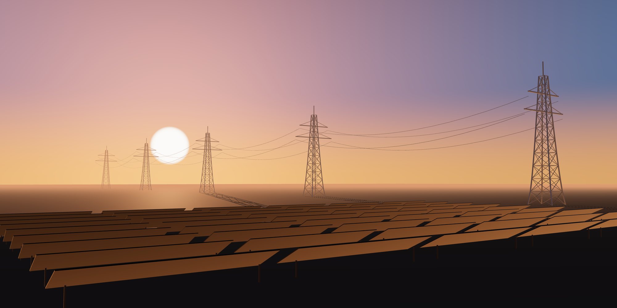
Steel structures for power plants, cooling equipment, renewable energy and electrical equipment platforms.
Solution Overview
Energy projects involve equipment supports, boiler and turbine buildings, cooling structures and supports for renewable generation. Loads, tolerances and interfaces are usually defined by equipment suppliers and must be coordinated early.
Typical Applications
- Power Plant Structures
- Cooling Equipment Supports
- Renewable Energy Supports
- Electrical Equipment Platforms
Sector challenges
Challenges We Engineer For
Late vendor data
Our engineering response We design with clearly stated load envelopes and adjustable details, then confirm vendor information at defined hold points before releasing shop drawings.
Vibration from rotating equipment
Our engineering response Dynamic analysis of support structures checks frequencies against operating speeds, and stiffness is added where it is most effective rather than everywhere.
Thermal movement and expansion
Our engineering response Slotted connections, sliding bearings and guided supports are detailed so ducts, piping and hot equipment can move without overstressing the frame.
Electrical clearances
Our engineering response Platform and support geometry is coordinated in the BIM model against electrical safety and maintenance envelopes before fabrication.
Engineering Solutions
Power and energy structures are designed around equipment rather than around architecture. Our engineering team builds analysis models that combine vendor interface loads, operating and upset conditions, thermal growth of ducts and piping, wind and seismic actions, and short-circuit or maintenance loads on electrical platforms. Dynamic checks for rotating equipment supports confirm that structural frequencies sit away from operating speeds, and the code basis is agreed with the owner engineer for the relevant market.
Connection design focuses on predictable stiffness and load transfer. Equipment base frames, boiler and turbine building connections and bracing to cooling structures are detailed so that vendor anchor patterns, slotted holes for thermal movement and shim allowances are respected. We coordinate continuously with equipment suppliers, because late changes to loads or bolt patterns are the most common cause of rework on energy projects.
Engineering Considerations
- Equipment vendor interface loads and tolerances
- Vibration and fatigue for rotating equipment
- Corrosion category for coastal or cooling-water environments
- Clearances for electrical safety and maintenance
One coordinated scope
From Engineering to Delivery on Site
Design optimization, fabrication, quality control, surface protection, export logistics and erection support managed as one scope, so interfaces between design, shop and site stay under control.
-
Design Optimization
The largest savings in energy structures come from freezing vendor data early and designing frames that tolerate later refinements without redesign. We group equipment supports into repeatable module types, rationalize platform levels across the plant, and use bracing layouts that keep maintenance corridors clear. For renewable projects such as solar mounting or battery enclosure supports, high repetition lets us refine member sizes and connection counts, which reduces tonnage, bolting labor and installation time across many identical units.
-
Fabrication Solutions
Typical members include heavy rolled columns, built-up girders for crane and boiler support, equipment base frames, gratings and handrailed platforms, and lightweight repetitive components for renewable plant. Welding follows the AWS D1.1 or EN 1090 execution class requirements specified, with machined or flattened bearing surfaces where equipment seats demand it. Anchor bolt templates and equipment base frames are fabricated to tight positional tolerances so they match vendor drawings, and modules are trial-fitted where interfaces between packages are critical.
-
Quality Assurance
An inspection and test plan defines hold points for equipment supports, base frames and primary connections. Materials are traced through mill certificates to each piece mark, weld inspection follows the NDT scope required for dynamic and primary members, and bolt-hole patterns at vendor interfaces are dimensionally verified against approved vendor drawings. Results, coating records and nonconformance closeouts are compiled into a QC dossier organized by plant area to suit the commissioning and handover structure.
-
Surface Protection
Energy assets operate in very different environments, from humid cooling tower areas and coastal plants to dry desert solar farms. We select coating systems to the ISO 12944 category for each zone, commonly C4 or C5 for cooling and coastal exposure, and use hot-dip galvanizing for platforms, gratings, cable supports and high-volume renewable components. Where steel sits near hot surfaces, heat-resistant coatings are specified, and fire protection is coordinated for turbine halls and transformer areas as required.
-
Export & Logistics
Energy projects are usually delivered in many packages, so we pack and ship by plant area and erection sequence to match the mechanical installation program. Equipment support frames and anchor templates are prioritized because foundation and vendor works depend on them. Repetitive renewable components are bundled for efficient container loading, while heavy girders and modules move as break-bulk. Packing lists, piece mark schedules and export documentation are aligned to the client package breakdown.
-
Erection Support
We support the erection contractor with erection drawings and sequences that align with equipment setting, so structural steel and mechanical works do not block each other. Our engineers can provide input to method statements for heavy lifts, temporary bracing of tall frames, and alignment of equipment base frames. Where agreed, we offer technical supervision or advisory visits during critical phases such as turbine building framing or equipment support setting.
What You Receive
Typical engineering, fabrication and quality documents for this type of structure. The final list is agreed for each project.
- Design basis with vendor load and interface register
- Structural and dynamic analysis calculations
- Equipment support and base frame drawings
- Anchor bolt layouts and templates
- BIM model coordinated with mechanical and electrical
- Inspection and test plan with QC dossier by plant area
- Coating and galvanizing records
- Erection drawings and sequence guidance
Global supply
Supplying Projects Worldwide
Engineering and documentation aligned with the codes, approvals and logistics of each market we supply.
-

Steel Structures for the United States
Structural steel for US projects designed and documented to AISC, ASCE 7 and AWS practice, with the submittals and traceability US…
-

Steel Structures for Canada
Steelwork for Canadian projects to CSA S16 design and CSA W59 welding, with welding-company certification and cold-climate material…
-

Steel Structures for Australia
Fabricated steel for Australian projects to AS 4100, AS/NZS 5131 and AS/NZS 1554.1, with construction category, cyclone wind actions and…
-

Steel Structures for New Zealand
Seismic-ready steelwork for New Zealand to NZS 3404 design and AS/NZS 5131 fabrication, with ductility, connection capacity design and…
-


Steel Structures for Europe
Structural steel components for European projects designed to the Eurocodes with National Annexes, and executed to EN 1090 with the…
-

Steel Structures for Japan
Steel supply for Japanese projects under the Building Standards Act framework, JIS-designated materials and fabricator grading, with…
-

Steel Structures for South Korea
Steelwork for Korean industrial and building projects aligned with the Korean Building Code and KS material standards, with fast-track…
-


Steel Structures for Southeast Asia
Regional steel supply across Singapore, Malaysia, Thailand, Vietnam, Indonesia and the Philippines, where each country's code basis…
-


Steel Structures for the Middle East
Steelwork for Gulf and Middle East projects specified to international codes by consultants, with extreme heat, sand and saline exposure…
-
Other International Markets
For markets not listed separately, we start from the project specification: governing code, material standards, inspection regime and…
Frequently Asked Questions
How do you handle equipment loads that are not final when design starts?
We agree a load envelope with the client and design to it, recording assumptions in a vendor interface register. When final vendor data arrives, we check it against the envelope at a defined hold point. This keeps fabrication moving while protecting against late changes.
Can you supply high-volume steel for solar or other renewable projects?
Yes. Repetitive renewable components suit optimized design and efficient fabrication with galvanized finishes. We refine connection details and packing to reduce installation time, and we plan shipments to match the client installation rate.
Do you design equipment foundations as well as steel supports?
Our scope covers the steel structure, connection design and anchor bolt layouts. We provide the reactions and anchor details that the foundation designer needs and coordinate closely so the interface is consistent.
Discuss Your Energy & Power Structures Project
Share your drawings and requirements. Our engineering team reviews the scope, the governing design code and the delivery conditions, then responds with the next steps.
Helpful to include
- Architectural or structural drawings, or a sketch of the layout
- Project location and site conditions
- Governing design code and any client specifications
- Key loads: cranes, equipment, wind or seismic data if known
- Required scope: design, fabrication, coating, supply, erection support
- Target schedule and delivery terms
Files attached to the request form are stored privately and are visible only to authorized staff.